Capabilities
Manufacturing Capabilities Designed Around Your Requirements.
The processes below are the ones named in the company brochure. Final feasibility depends on material type, thickness, component dimensions, tolerances, tooling, and the specific machine configuration.
01
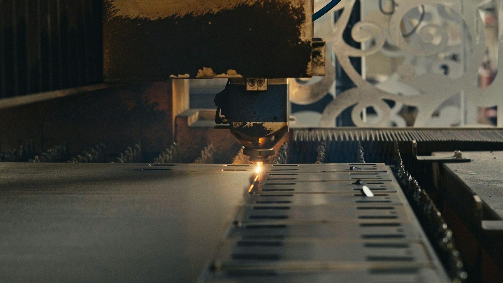
Laser Cutting
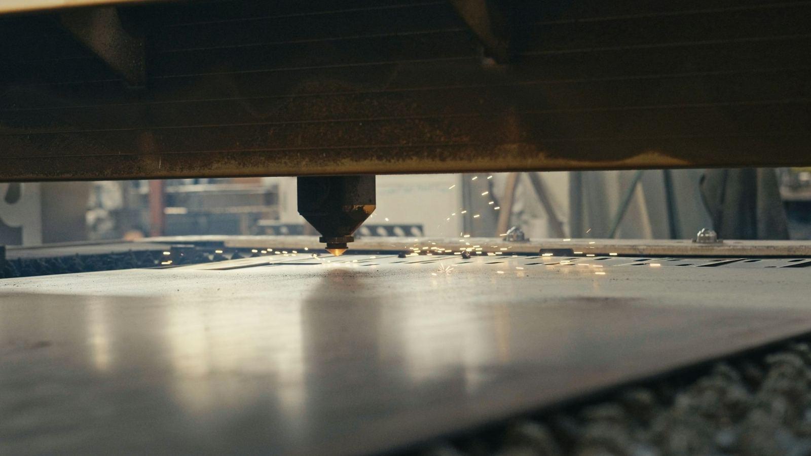
Nirman Industries uses a 3 kW laser cutting machine from UltraCut. The company brochure describes it as supporting precision cutting of a variety of sheet metal materials and thicknesses, with accurate profiles, clean edges, and complex component shapes.
Process considerations
- Component profile and nesting implied by the drawing
- Material details where the customer provides them
- Edge condition expected on the finished part
- How the cut profile will be bent, pressed, or welded afterward
Typical component examples
Profiled plates · Slotted and perforated patterns · Complex flat blanks · Panels prepared for forming
02
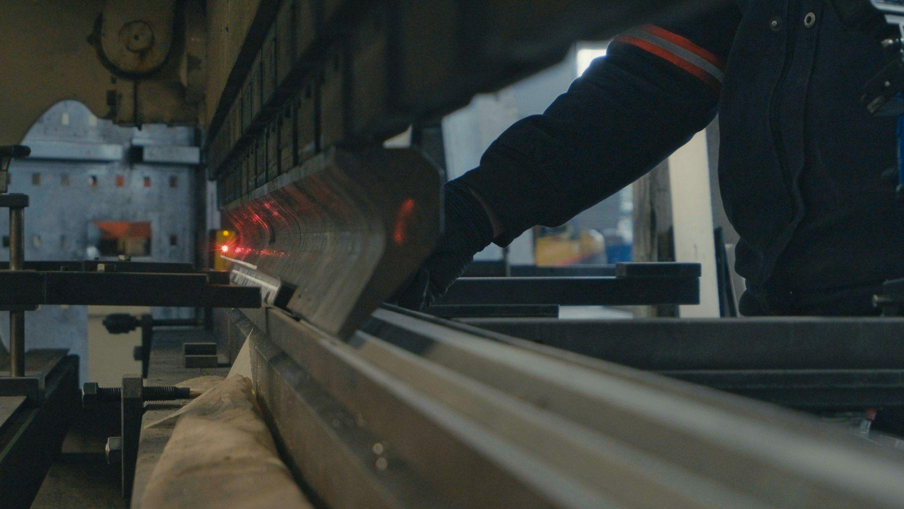
Sheet Metal Bending & Forming
Bending and forming are carried out on a press brake from Siddhapura Machine Tools. The brochure describes production of components with consistent angles and dimensional accuracy for a variety of industrial requirements.
Process considerations
- Bend lines, angles, and inside radii shown on the drawing
- Bend sequence relative to holes and cutouts
- Material and thickness, where specified
- How formed parts will assemble with other components
Typical component examples
Angles and channels · Brackets · Formed covers · Trays and simple enclosures
03
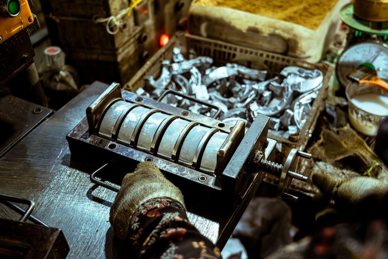
Pressing & Stamping
The brochure includes a power press for pressing and stamping operations on suitable components. No manufacturer, tonnage, or bed size is stated, so those details are not listed here. Whether a part is suitable is confirmed from the drawing and the job specification.
Process considerations
- Whether the feature is practical as a pressing operation
- Tooling implied by the component geometry
- Material and thickness, where provided
- How pressed parts fit the rest of the fabrication
Typical component examples
Pressed features on suitable parts · Formed details · Components prepared for later assembly
04
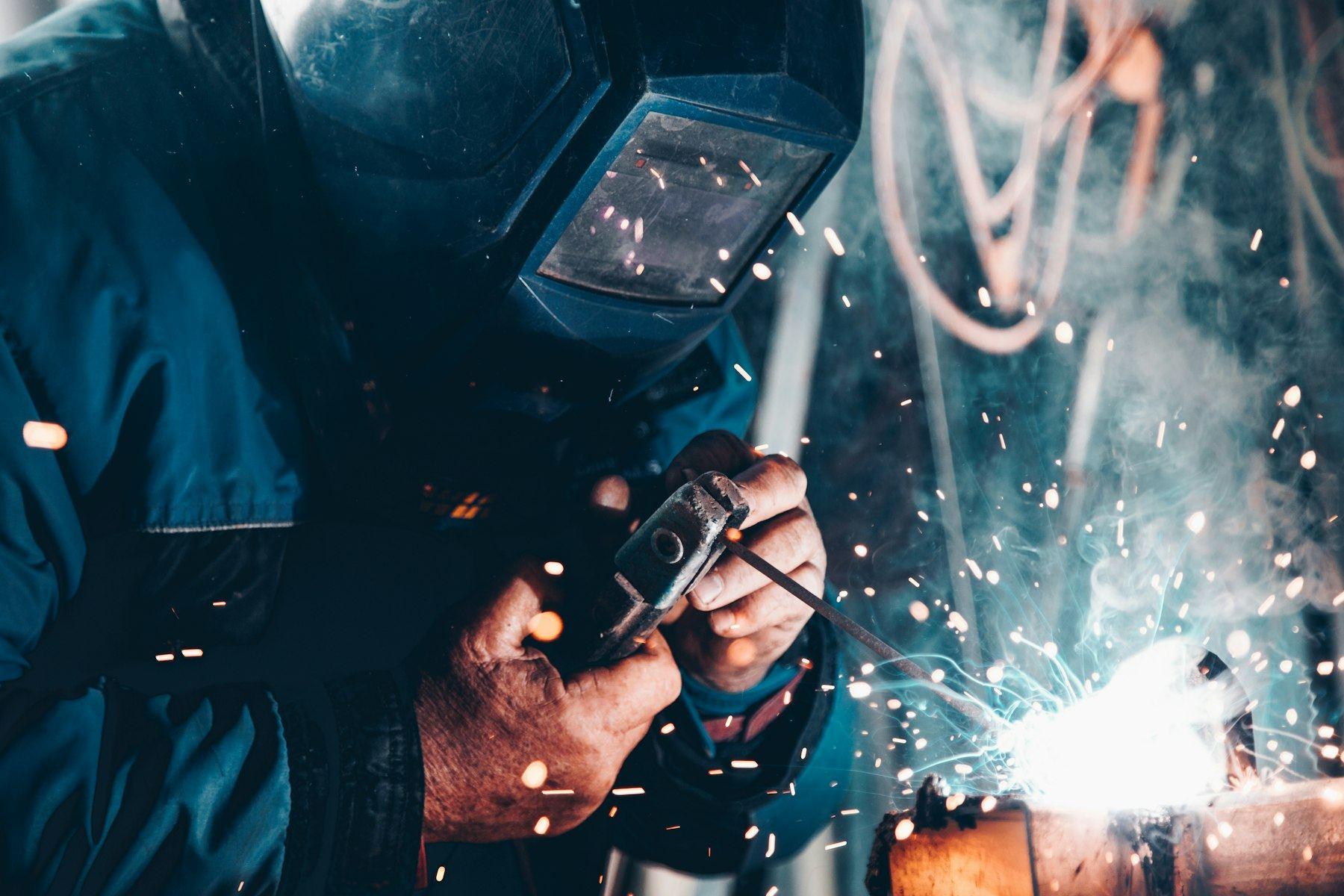
MIG/ARC Welding
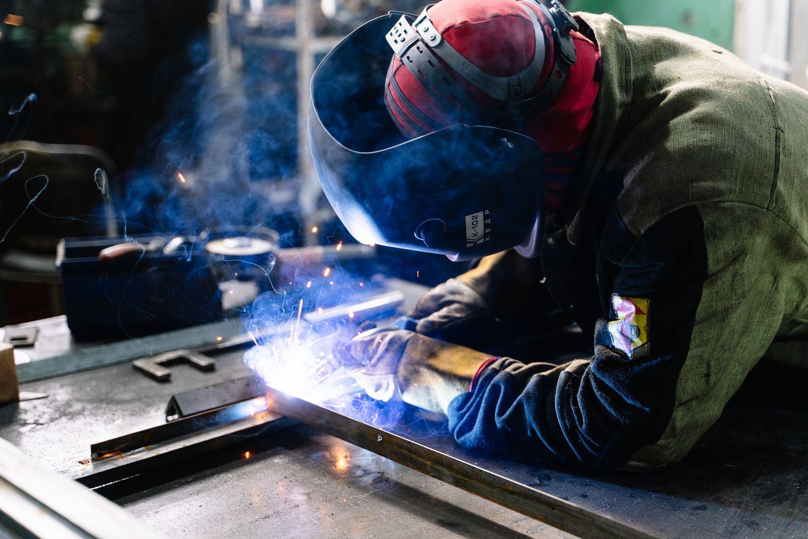
MIG/ARC welding is used for fabrication and assembly work that needs strong, durable welded joints. The brochure describes the equipment for heavy-duty fabrication and structural work across a range of metal components.
Process considerations
- Joint type and weld locations shown on the drawing
- How parts are cut and formed before they are joined
- Access for welding and the intended assembly sequence
- Questions on the drawing are clarified before work proceeds
Typical component examples
Welded frames · Fabricated assemblies · Brackets joined to plates · Structural fabrication
05
Engineering Drawing & Production Understanding
Engineering drawings are the starting point for the component. The brochure describes a review of the available drawings and specifications so the team can understand the part and select suitable processes.
Process considerations
- Review of component profiles and dimensions
- Understanding of bending, forming, and joining requirements
- Attention to specified tolerances and material details when provided
- Clarification of drawing or specification questions before proceeding
- Verification against applicable customer requirements where inspection is defined
Typical component examples
Customer drawings · Marked-up profiles · Bending and joining notes · Material callouts supplied with the inquiry
06
Custom Fabrication
Cutting, forming, pressing, and welding can be considered together when a component needs more than one operation. The combination depends on the drawing, dimensions, material requirements, tooling, and the job specification. Final feasibility is assessed for each inquiry.
Process considerations
- Which listed processes the geometry actually needs
- Material type and thickness
- Component dimensions and specified tolerances
- Tooling and machine configuration
Typical component examples
Multi-process brackets · Welded sheet assemblies · Formed panels · Job-specific fabricated parts
Related
See the equipment and the working approach.
Machinery details stay within what the brochure publishes. The quality page explains drawing review and verification without claiming a certified quality system.
Photographs on this page illustrate the process. They are not verified pictures of Nirman Industries equipment or customer work.
Bring the drawing.
Share the component, material notes, and quantity so the team can consider a suitable process.
